

Services/Automated Ultrasonic Testing (AUT)
Automated Ultrasonic Testing 100 AUT systems ready to deploy.
Putting a pipeline into service is a beast of an accomplishment.
Hundreds of people, millions in iron, and a firing line that only moves as fast as welds get cleared. Every hour inspection holds the spread, the whole beast stands still — and the meter keeps running.
Time is money
Welds a day, cleared at the weld
A typical published cross-country AUT production rate on automatically welded spreads — keeping pace with mechanized welding.1 Encoded PAUT / AUT delivers dispositions at the weld — no film, no darkroom, no next-morning review. The spread moves at the speed of clearance.
Who’s waiting while the film develops?
- Welding crews
- Coating
- Lowering-in
- Backfill
- Equipment & iron
- The schedule
On heavy-wall tie-ins, the waiting costs the Owner/Operator money — specialized crews standing by through long exposures and film development on the most expensive welds of the job. PAUT tie-ins get disposition at the weld.
So why is the U.S. still waiting?
It’s already accepted
API 1104 recognizes mechanized UT, and its Annex A alternative acceptance criteria — based on engineering critical assessment (ECA) — are built around the flaw-height sizing that radiography cannot provide. The code isn’t the obstacle.
The rest of the world already switched
Mainline spreads in Australia, the Middle East and Europe — and major subsea lay vessels — run AUT as a matter of course.
Common on big U.S. spreads — the tie-ins are the gap
AUT already runs on some of the biggest U.S. mainline spreads. Extending AUT and PAUT to the tie-ins is the next step — it increases the speed of clearance and reduces the Owner/Operator’s cost.
1. “A typical cross country production rate of over 120 welds a day is achieved at projects where automatic welding is applied.” R. van Agthoven and J.A. de Raad (Röntgen Technische Dienst), “Reliability of Mechanised UT Systems to Inspect Girth Welds during Pipeline Construction”, ECNDT 1998, NDT.net. Industry-published rate, not a Prime project measurement.
Mainline AUT. Semi-automated UT for everything else.
Mainline: mechanized AUT
Encoded phased array and TOFD channels on a band scanner for production girth welds, with results that support API 1104 Annex A alternative (ECA-based) acceptance criteria where the project specifies them.
Tie-ins, repairs & fittings: semi-automated UT
Encoded phased array (PAUT) and TOFD on a hand-driven scanner for tie-ins, repair welds, fittings and short runs where an AUT band will not fit — the same encoded, reviewable record.
Certified to a written practice
UT technicians certified to our written practice under ASNT SNT-TC-1A / ANSI/ASNT CP-189 — Levels I and II employer-certified, with ASNT Level III oversight.
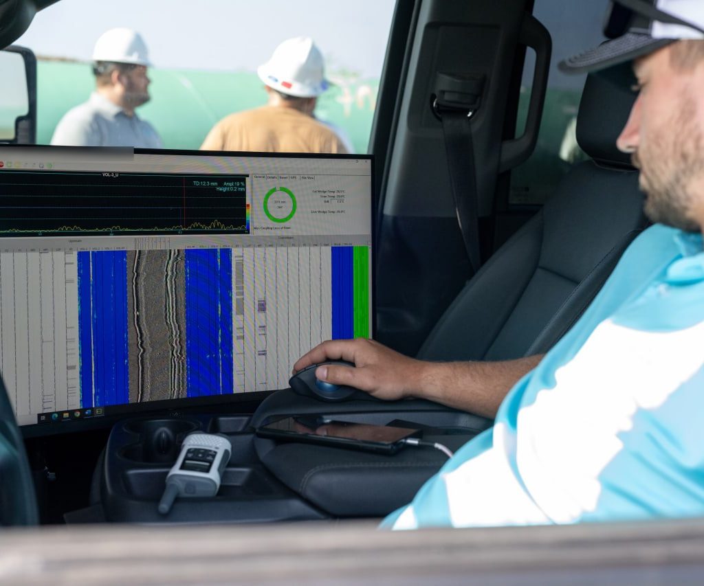
AUT in the field
AUT on a live spread: calibrating the unit on the right-of-way.
PAUT: The Entire Weld Volume, From Every Angle
How an automated scanner reads a girth weld
Electronically steered, focused beams
Dozens of refracted angles from one probe pair interrogate the fusion line at near-normal incidence — where radiography, shooting through the weld, can under-call the same planar flaw.
Full weld + HAZ coverage in one pass
One encoded circumnavigation captures root to cap, both fusion faces, and the heat-affected zone.
TOFD tip diffraction
Measures flaw height from crack-tip signals — the industry benchmark for through-wall sizing.
Immediate, on-site disposition
The technician reads the data as the scanner completes its pass — accept/repair in minutes, not next-morning film review.
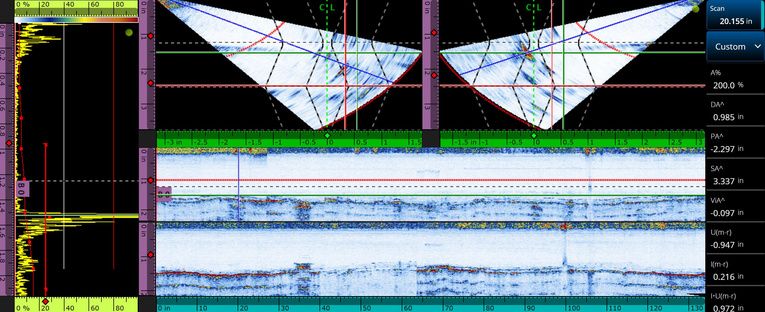
Detect. Size. Record.
Detect & size
S-scans and C-scans pinpoint and measure discontinuities — toe & root cracks, lack of fusion, porosity, slag.
Immediate
Results are read at the weld, so dispositions happen in real time and the spread keeps moving.
Auditable record
Every weld stored as encoded digital data — instantly shareable and ready for QA/QC and audits.
From a 2-D Shadow to an Encoded Volumetric Dataset
Radiography — 2-D projection
One flattened density image per exposure. Tells you an indication exists and how long it is. Cannot tell you how tall it is, how deep it sits, or whether it is planar — the difference between a cosmetic call and a cut-out.
PAUT + TOFD — volumetric, encoded
Three spatial dimensions + encoded position. A-, B-, C- and S-scans map every indication in X, Y and through-wall Z, tied to a position encoder — a complete dataset you can re-open, re-analyze, and audit for the life of the asset.
Every Weld Becomes a Permanent Digital Asset
Full raw data, not just reports
Complete encoded datasets: A/B/C/S-scans, TOFD, calibration and scan parameters.
Weld-by-weld disposition log
Accept/repair with indication type, position, length and height — same day.
Audit-ready archive
Re-open any weld years later for integrity management, dig verification or regulator response — the original encoded data, not a re-shoot.
Supports operator traceability requirements
Digital records tie each joint to procedure, technician, equipment and calibration.
Related resources
Put automated ultrasonics on your next spread.
The spread moves at the speed of clearance. Tell us about the job.